

جدول المحتويات
A crane rail in an underground mine is more than a suspended track for moving equipment. It forms part of an integrated transportation system in which roadway geometry, roof conditions, gradient, load, turning radius, braking, clearances, and the selected monorail crane must work together.
For underground coal mines in particular, poor rail layout can restrict equipment movement even when the monorail itself has sufficient traction and lifting capacity. A successful design therefore begins with the mine roadway rather than with the crane specification alone.
Key takeaways:
- Design the crane rail around actual roadway geometry, gradients, curves, intersections, and roof conditions.
- Match track geometry to the horizontal and vertical turning capability of the selected monorail crane.
- Calculate operational loads rather than considering only the weight of the transported material.
- Verify suspended clearance around ventilation ducts, cables, pipelines, support systems, and workers.
- Treat gradients, braking requirements, and load security as one engineering problem.
- Plan inspection, maintenance, rail extension, and equipment recovery before installation.
- Select the monorail crane and rail system together rather than as separate pieces of equipment.
What Is a Crane Rail in Underground Mining?
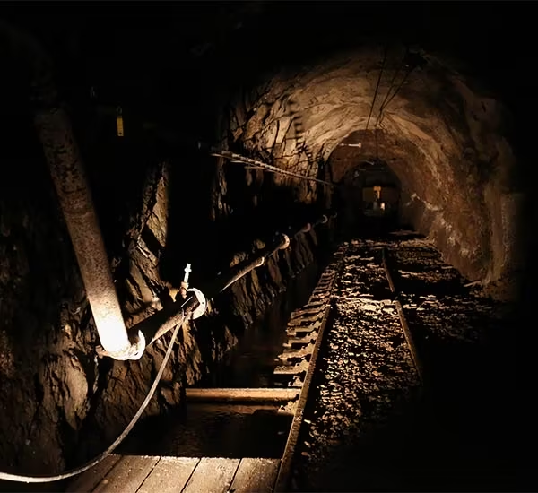
A crane rail is the structural guideway along which a suspended lifting or transportation unit travels. In underground mining, the system is commonly mounted above the roadway so that transportation can occur without consuming as much floor space as conventional wheeled haulage.
The broader principle is related to a monorail, where a vehicle is guided or suspended by a single rail or beam. Mining applications, however, introduce much more demanding conditions: variable roof profiles, restricted cross-sections, gradients, heavy machinery loads, explosive environments, water, dust, and continuously changing working areas.
A mining crane rail can support the movement of:
- roadway support materials;
- hydraulic supports;
- electrical equipment;
- drilling tools;
- cables and pipes;
- maintenance components;
- long or irregular loads;
- machinery assemblies;
- workers where the approved system is designed for personnel transport.
Because the suspended rail becomes part of the mine’s logistics infrastructure, its layout should be considered together with the complete auxiliary transportation equipment نظام.
Why Crane Rail Layout Matters Underground
Surface lifting equipment often operates in relatively predictable spaces. Underground transportation is different because the roadway itself becomes a major design constraint.
A rail may need to follow several hundred or several thousand meters of changing tunnel conditions. During that distance, it may encounter increasing gradients, tight intersections, support structures, deformation zones, equipment stations, ventilation installations, transfer points, and active mining faces.
Clearance is limited in three dimensions
An underground roadway has usable width and height limits.
The rail, suspension elements, monorail body, lifting equipment, transported load, existing pipelines, cables, ventilation ducts, roof bolts, and workers all compete for space.
The important dimension is therefore not simply roadway height. Engineers need to determine the actual transportation envelope of the complete crane-and-load combination.
Ground conditions may change over time
The roof profile that exists during installation may not remain unchanged throughout the service life of the rail.
Convergence, roof deformation, local support movement, floor heave, and rehabilitation work can reduce operating clearance. A crane rail design should therefore consider expected roadway behavior instead of relying only on the initial excavation profile.
Transportation safety depends on infrastructure
The U.S. National Institute for Occupational Safety and Health notes that mining workers often operate near moving machinery in confined and visibility-limited environments, making machinery and powered-haulage interaction an important safety concern. The agency’s mining machinery and struck-by injury research highlights the importance of equipment design, controls, visibility, and proximity management.
A crane rail layout that produces blind approaches, insufficient clearance, abrupt transitions, or difficult stopping zones can create operational problems that cannot be solved simply by selecting a more powerful crane.
7 Factors That Determine a Good Crane Rail Layout
1. Roadway cross-section and available clearance
Start with a detailed roadway profile.
Measure:
- clear roadway width;
- clear roadway height;
- arch or roof profile;
- roof support protrusions;
- cable trays;
- water and compressed-air lines;
- ventilation ducts;
- conveyor structures;
- pedestrian routes;
- equipment parking areas.
The suspended load envelope should then be plotted through the roadway.
This is particularly important when long components are transported. A load that fits through a straight tunnel may sweep into a rib, support structure, or pipe when the crane enters a curve.
Minimum clearance should not be treated as a single number
Different mines operate under different regulations, equipment configurations, and risk controls. Therefore, a universal clearance value should not be copied from another project.
Instead, determine clearance from the largest expected load, equipment movement, rail alignment, roadway deformation allowance, and local mine requirements.
2. Roadway gradient
Gradient has a direct effect on traction and braking demand.
As the roadway becomes steeper, the monorail must overcome a greater component of gravitational resistance while travelling uphill. During downhill transportation, the braking system must control the combined mass of the crane and load.
This makes gradient one of the first parameters that should be exchanged between mine engineers and equipment suppliers.
For example, YMHB’s رافعة أحادية السكة للتعدين مقاومة للهب تعمل بالبطارية من سلسلة DX lists a maximum gradeability of 15° across the published DX40–DX120 configurations. Its published horizontal turning radius is 4 m and vertical turning radius is 10 m.
ال رافعة أحادية السكة تعمل ببطارية ليثيوم من سلسلة DL lists a maximum gradeability of 25°, together with a 4 m horizontal and 10 m vertical turning radius for the published models.
These values illustrate why track and machine selection should be performed together. They should not be interpreted as universal design limits for every installation; actual permissible operation depends on the complete configuration, transported load, rail system, braking arrangement, mine conditions, and approved engineering requirements.
3. Horizontal curves
A crane rail rarely follows a perfectly straight roadway.
Intersections, crosscuts, chambers, equipment stations, and geological deviations may introduce horizontal curves.
Curve design affects:
- vehicle articulation;
- wheel or drive-unit contact;
- load swing;
- traction resistance;
- clearance;
- component stress;
- travel speed.
An important mistake is checking only whether the machine itself can pass through the curve.
A long suspended load may create a considerably larger swept path than the monorail body.
Check the complete transportation envelope
Before finalizing a curve, simulate or calculate the movement of:
- the front of the train;
- drive units;
- lifting beams;
- suspended load;
- rear equipment;
- hoses or electrical interfaces where applicable.
This produces a more realistic clearance assessment.
4. Vertical curves and roof profile changes
Vertical curvature is equally important but sometimes receives less attention.
Changes from level roadway to gradient, local roof undulation, roadway intersections, and rehabilitation zones can create vertical transitions.
If the transition is too abrupt, articulation limits may be reached or suspended equipment may lose necessary clearance.
The YMHB رافعة أحادية السكة كهربائية DDD30 provides a useful example of why this parameter matters. Its published technical data lists a horizontal passing radius of 4 m and vertical passing radius of 8 m, with a maximum lifting weight of 10 t.
The rail route therefore needs to be checked against the actual machine being installed, not against a generic concept of an underground monorail.
How Load Affects Crane Rail Design
The transported component’s static weight is only the beginning of a crane rail load assessment.
Engineers should consider the complete operating condition.
| Design Factor | لماذا يهم | What Should Be Verified |
|---|---|---|
| Equipment self-weight | Permanent load acting through the system | Crane, drive units and lifting assemblies |
| Transported load | Main variable operating load | Maximum and typical loads |
| Load distribution | Uneven loads change wheel and suspension forces | Center of gravity and lifting points |
| Gradient | Changes traction and braking demand | Maximum operating slope |
| Acceleration and braking | Produces dynamic force | Operating and emergency conditions |
| Curves | Add resistance and alter load position | Horizontal and vertical radii |
| Rail suspension spacing | Determines load transfer to roof support | Approved structural arrangement |
| Long loads | Increase swept path | Curve and intersection clearance |
| Roadway deformation | Can change rail alignment | Inspection and adjustment strategy |
Center of gravity
Two loads with the same mass can behave very differently.
A compact motor and a long hydraulic support assembly may impose different demands on lifting points, stability, and clearances.
Determine:
- load dimensions;
- center-of-gravity position;
- lifting-point locations;
- possibility of shifting during transport;
- allowable orientation through curves.
Dynamic loading
Starting, stopping, braking, and passing through irregular track sections create forces above a purely static condition.
Rail design should therefore follow the applicable engineering standard and approved load combinations rather than relying solely on nominal payload.
Crane Rail Suspension and Roof Conditions
Because a mining monorail is suspended from the roadway roof or engineered support structure, rail performance depends on the reliability of the supporting ground-control system.
The design process should distinguish between:
- capacity of the rail;
- capacity of rail connectors;
- capacity of suspension components;
- capacity and spacing of suspension points;
- capacity of roof anchorage;
- surrounding rock or support condition.
A strong crane rail cannot compensate for an unsuitable suspension foundation.
Examine local roof conditions
Important observations include:
- bedding separation;
- fractured zones;
- faults;
- water damage;
- roof cutters;
- damaged bolts;
- deformed steel support;
- excessive convergence.
Where the roadway already requires rehabilitation, rail installation should be coordinated with the mine’s ground-control plan.
YMHB also supplies equipment for roadway excavation, bolting, support and maintenance in addition to underground transportation. This makes it useful to evaluate the crane rail as part of the mine’s broader underground mining equipment system rather than as isolated infrastructure.
Crane Rail Design for Curves, Junctions and Transfer Areas
Straight sections are normally the simplest part of the route. Junctions and operational stations deserve more engineering attention.
Intersections
At intersections, check whether the transported load can move through the full turn without interfering with:
- roadway ribs;
- supports;
- ventilation equipment;
- cables;
- other vehicles;
- pedestrian paths.
If large loads regularly move through the area, the intersection may need a larger clearance envelope than adjoining roadway sections.
Loading and unloading stations
Loading points should provide sufficient space for controlled lifting and positioning.
Consider:
- stable load staging area;
- worker access;
- visibility;
- communications;
- hook or lifting-beam movement;
- emergency escape routes;
- rail stopping position.
Maintenance and recovery locations
No transportation system operates indefinitely without inspection or maintenance.
The layout should identify places where equipment can be inspected, isolated, recovered, or removed without blocking critical mine traffic.
Planning these points during design is much easier than improvising them after installation.
Crane Rail and Monorail Crane Selection Must Be Integrated
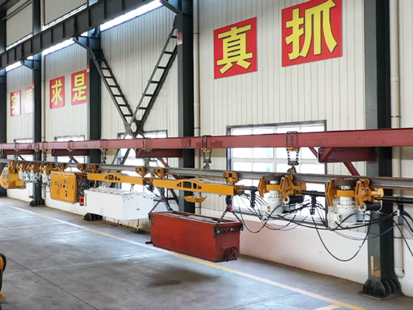
A common procurement mistake is designing the track first and selecting the monorail afterward.
The better approach is to create a system-level specification.
Compare at least:
| معلمة | Rail Design Question | Equipment Selection Question |
| Gradient | How steep is the route? | Can the crane provide required traction and braking? |
| Horizontal curves | What is the minimum radius? | Can the vehicle articulate through it? |
| Vertical curves | How quickly does roadway slope change? | What vertical radius can the machine negotiate? |
| Load | What forces reach rail and suspension? | What traction/lifting configuration is required? |
| Clearance | Where can the rail be positioned? | What is the machine and load envelope? |
| Power | Where is electrical infrastructure available? | Electric, battery or another approved configuration? |
| Route length | How long is the transportation cycle? | Is energy capacity suitable? |
| Expansion | Will the heading advance? | How easily can track and equipment be extended? |
For mines comparing different power architectures, YMHB’s existing دليل شراء أنظمة الرافعات الأحادية للتعدين explains electric, conventional battery-powered, and lithium battery-powered configurations in more detail.
Electric vs Battery Monorail Systems
The crane rail itself cannot be designed independently of the vehicle’s energy system.
Electric monorail crane
An electric system may suit routes with suitable mine electrical infrastructure and relatively predictable operating paths.
The DDD30, for example, uses wireless flameproof remote control according to YMHB’s published product information and is designed around a compact configuration for confined underground movement.
Flameproof battery-powered monorail crane
Battery operation can reduce dependence on a continuously connected power supply along the transport route.
The DX Series is designed for underground mining transportation and includes published models ranging from 40 to 120 kN maximum traction force. YMHB also states that the platform supports reverse charging during downhill movement and provides interfaces for remote monitoring and intelligent operation.
Lithium battery-powered monorail crane
The DL Series is another option for routes where mobility and charging strategy are important. YMHB lists quick charging of approximately 1.5–2 hours and published maximum traction-force configurations from 40 to 120 kN.
The correct choice should still be based on mine-specific duty cycles rather than a single specification.
Safety Considerations for Underground Rail Crane Routes
A safe crane rail route should make predictable operation easier.
MSHA’s guidance on powered haulage safety emphasizes the continuing importance of transportation-related hazards in mining. Its underground haulage guidance also highlights equipment condition, brakes, visibility, operator training, roadway conditions, warning devices, and load security as important controls.
For a suspended rail crane system, practical design considerations include:
Braking zones
Avoid planning routine stopping locations where gradients, curves, or poor visibility unnecessarily increase risk.
Visibility
Operators and workers should be able to recognize approaching equipment and understand traffic status at intersections or restricted areas.
Emergency access
The crane and load should not eliminate required emergency passage.
Load security
Long or irregular components should have engineered attachment arrangements that control movement during acceleration, braking, curves, and gradients.
تواصل
Where workers coordinate loading, transport, and unloading, the operating procedure should define communications and responsibility clearly.
YMHB’s existing article 5 نصائح قوية لسلامة منجم الرافعات للعمليات تحت الأرض discusses additional issues including remote control, equipment monitoring, power-source selection, passability, and underground crane safety management.
Common Crane Rail Design Mistakes
Selecting the rail by maximum load only
Payload capacity is important, but it does not define the complete system.
Gradient, dynamic loading, turning resistance, braking, suspension, roadway clearance, and expected route changes can be equally important.
Ignoring the largest load dimensions
The heaviest load may not be the most difficult to transport.
Long, wide, or offset loads can become the limiting factor at curves and intersections.
Using the roadway centerline automatically
The geometrical center of a tunnel is not always the best position for the rail.
Ventilation equipment, cable trays, pipelines, roof support, conveyors, maintenance access, and future installations may justify an offset route.
Forgetting future roadway deformation
A rail that has adequate clearance immediately after installation may encounter problems later if the roadway converges.
Inspection and adjustment provisions should therefore be part of the design.
Copying another mine’s track layout
Even mines using similar monorail cranes can have very different:
- roof geology;
- gradients;
- roadway dimensions;
- transportation loads;
- support systems;
- ventilation arrangements;
- operating procedures.
Existing projects provide useful references, but they do not replace site-specific engineering.
Designing without the monorail specification
If the track radius, gradient, or clearance does not match the machine, expensive modification may be required later.
The selected vehicle should therefore be involved in the layout process as early as possible.
A Practical Crane Rail Planning Checklist
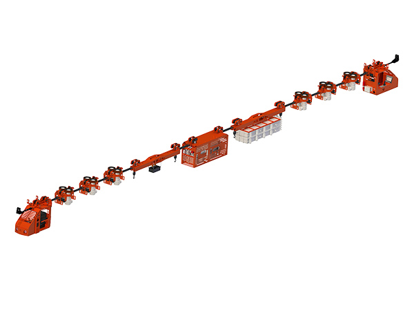
Before approving a route, collect the following information.
Roadway data
- roadway width and height;
- roof profile;
- route length;
- maximum gradient;
- horizontal curve radii;
- vertical transitions;
- intersections;
- deformation history;
- support system.
Transport data
- maximum load;
- typical load;
- longest component;
- widest component;
- lifting points;
- center of gravity;
- transport frequency;
- required cycle time.
Monorail data
- maximum traction force;
- maximum permitted gradient;
- braking capability;
- horizontal turning radius;
- vertical turning radius;
- vehicle length;
- vehicle width;
- lifting arrangement;
- energy system;
- control method.
Infrastructure data
- electrical supply;
- charging locations;
- ventilation;
- communication network;
- pedestrian routes;
- loading stations;
- maintenance areas;
- emergency access.
When this information is available, equipment selection becomes much more accurate.
Building the Crane Rail Around the Entire Mining Workflow
The best crane rail does not simply allow a monorail to travel from point A to point B.
It should support the actual underground workflow.
For example, a roadway development operation may require transportation of:
- roof bolts;
- mesh;
- cables;
- drilling tools;
- machine parts;
- hydraulic equipment;
- maintenance materials.
A transport delay at the development face can reduce the benefit of fast excavation or mechanized bolting.
For this reason, underground logistics should be planned together with excavation and support equipment. YMHB’s mining transportation solutions combine monorail products with broader auxiliary transportation and underground equipment applications.
Mines evaluating transportation alternatives can also review the site’s Mining Transportation Vehicles Comparison, which compares multiple equipment configurations and discusses factors such as traction, turning radius and underground operating conditions.
When Should a Crane Rail Layout Be Re-Evaluated?
Rail routes should not be treated as permanent simply because installation has been completed.
Re-evaluation may be appropriate when:
- roadway convergence increases;
- the transported load becomes heavier or longer;
- a new monorail crane is introduced;
- the route is extended;
- support conditions change;
- intersections are modified;
- electrical or ventilation infrastructure is relocated;
- abnormal wear appears repeatedly;
- derailment or braking events occur;
- production requirements change.
Repeated component failure should be investigated as a system problem rather than solved only by replacing the failed part.
For example, unusual wear may result from alignment, curvature, suspension movement, excessive load, or roadway deformation.
التعليمات
What is a crane rail used for in underground mining?
A crane rail provides the suspended guideway used by a mining monorail or rail crane to transport equipment, support materials and other loads through underground roadways. Because it keeps much of the transportation system above floor level, it can be useful where floor conditions, congestion or limited roadway space make conventional transport more difficult.
How do I determine the correct crane rail turning radius?
Start with the minimum horizontal and vertical turning radii specified for the selected monorail crane, then evaluate the swept path of the complete machine and its longest expected load. Roadway width, support structures, pipes, cables and ventilation equipment must also remain outside the required transportation envelope.
Can a crane rail be installed in a steep mine roadway?
Yes, suspended monorail systems can be used on inclined routes, but permissible gradient depends on the selected equipment, traction, braking system, load, rail arrangement and mine requirements. For example, YMHB publishes different gradeability values for its DX and DL monorail platforms, demonstrating why slope should be considered during equipment selection rather than after track installation.
What information is needed before selecting a mining monorail crane?
Provide roadway width and height, route length, maximum gradient, horizontal and vertical curves, largest load dimensions, maximum load mass, roof conditions, available power, transport frequency and environmental requirements. This data allows the crane, rail geometry, traction configuration and lifting arrangement to be matched as one transportation system.
How often should an underground crane rail be inspected?
Inspection intervals should be established through the mine’s approved maintenance and risk-management procedures. High-use sections, curves, junctions, suspension points and areas affected by roadway deformation generally require particular attention. Alignment changes, loose connections, abnormal wear, support movement or damaged components should be investigated before they develop into larger transportation problems.
خاتمة
Crane rail design in underground mining is fundamentally a system-integration task.
The rail must work with the roadway, roof-support structure, gradients, curves, loads, power infrastructure, monorail crane, operational procedures and future mine development.
A reliable design therefore begins by answering several practical questions:
What must be transported?
How heavy and large are the loads?
How steep is the roadway?
What are the tightest horizontal and vertical curves?
How will the rail be supported?
What clearance will remain after roadway deformation?
Which monorail configuration can safely operate along the complete route?
Only after these conditions are understood should the final crane rail and monorail crane configuration be selected.
YMHB provides auxiliary transportation equipment including flameproof battery-powered, electric and lithium battery-powered mining monorail crane systems for different underground transportation requirements. For a specific project, roadway dimensions, gradient, turning radius, required traction, transported loads and operating environment should be reviewed together so that the rail route and equipment configuration can be matched to the actual mine rather than to a generic specification.